Rugged RF & Optical Solutions Over OpenVPX Prepare Mil/Aero Customers For the Next Generation of System Performance
Military and Aerospace embedded computing systems are evolving quickly and the industryis striving to meet the changing requirements. One area of significant advancement is the OpenVPX backplane arena, with a strong push from the Army’s CERDEC with the CMOSS (C4ISR/EW Modular Open Suite of Standards) effort, Navy’s NAVAIR with HOST (Hardware Open System Technologies), and Air Forces’ AFLCMC with FACE (Future Airborne Capability Environment) and SOSA (Sensor Open Standard Architecture) to move jointly toward an open, compatible architecture. Okay, enough acronyms. In short, the industry is adding more power and bandwidth/performance to OpenVPX-based systems.
More bandwidth, performance
There is a broad range of backplane speed requirements for tomorrow’s advanced systems. Many applications will work just fine for years to come with 10GbE and PCIe Gen2 speeds across the slots of the system. But, others have requirements where speed is paramount. The approximately 12.5 Gbps limitation of the current MultiGig RT2 OpenVPX connector won’t cut it for 100GbE (4 lanes x 25 GbE) or even PCIe Gen4 (16 Gbps). The good news is the new RT3 version of the connector is backwards compatible (from a Plug-In Module perspective) and is designed to 25 Gbps speeds.

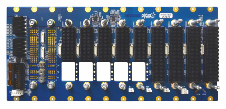
It isn’t only the speed across the OpenVPX backplane connectors that is increasing. VITA 66 adds various optical connector options and VITA 67 adds RF connector options. This allows a blind-mate optical and/or RF interface to be used on OpenVPX modules. There are all types of requirements and configurations with these subsets. This requires a lot more configuration for backplanes. To help alleviate this challenge, development backplanes have been developed for some of the configurations. See Figure 1. Those seeking to prepare for SOSA/HOST or other requirements are utilizing various combinations of these interfaces. While SOSA calls out for aggressive implementations for advanced cooling, including airflow going directly through the pluggable modules, it seems likely that a wide range of thermal management options will be utilized. We can take a lesson from the AdvancedTCA architecture from the early 2000’s. The specification required full redundancy throughout the shelf (chassis platform). However, as the market evolved implementations emerged with a single shelf manager, AC (single and dual) power supplies, etc. The cooling configurations evolved from front to rear to side-to-side airflow and even some conduction-cooled versions. It seems likely that the rugged MIL OpenVPX market will evolve to “what works” regarding the cooling implementations. In some cases, the more powerful standard cooling approaches can be highly leveraged (see more on this below). The new VITA specifications where the airflow is channeled on the outside of the module looks to become an easy middle ground. The change to current chassis designs is minimal to direct air through these channels on the outside of the module. The more complex route is an airflow-through-module approach, where the air would be channeled into a module cannister. This would require more significant changes to the cooling approach for an air-cooled system, but the principle is similar to that of an ARINC600 enclosure, where an external air source channels the air in a duct to enhance the cooling of the sealed unit.

VITA 46.11 System Management
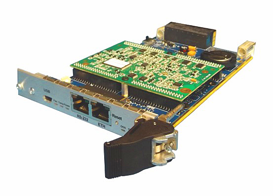
Utilizing the system management feature of VITA 46.11 is another target of theses types of applications. The chassis manager mainly monitors the power and system thermals. For example, it can monitor each of the power rails and provide an alarm function for voltage levels that fall below the defined acceptable range. An OpenVPX chassis manager can be used to monitor cooling zones with thermal sensors located in the chassis. The fan control function can automatically speed up as needed to cool each zone properly. Figure 2 shows an example of an OpenVPX Chassis Manager. This design plugs into the P0 (power and system management) connector of any OpenVPX backplane. Various front panels can be utilized to fit the needs of the system such as 3U or 6U and 4HP (0.8”) wide or 5HP (1.0”) wide. Additionally, a version in wedge locks for conduction cooling is also possible. For more I/O and customization, a P1 and/or P2 connector can be added.

Rugged Chassis Designs
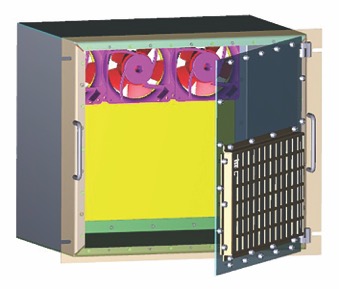
To meet the MIL specifications, the chassis needs to have a few key elements. First, the enclosure must be ruggedized with thicker rails, metal sidewalls, etc, to handle the shaking of the system. With requirements to operate in often -40 to +70C or even higher temperature levels, MIL-grade fans need to be employed. The chassis manufacturer can do thermal simulation to approximate the CFM and cooling options to meet each application’s needs. The subrack is typically recessed inside the chassis with an EMI protective door that allows enough air intake while restricting emissions. In most cases, an AC or DC VITA 62 compliant PSU will be utilized. These power supplies are compliant to the MIL specifications and some have special options for airborne requirements. See Figure 3 for a model of an 8U MIL rugged OpenVPX chassis. The chassis is designed to accept up to 15 OpenVPX slots and 1 pluggable VITA 62 PSU slot or various configuration options therein. A similar approach can be employed for 3U modules in a 5U high MIL chassis. With three high CFM MIL grade fans, the chassis can dissipate a significant amount of heat. The I/O cabling is an important issue in order to ensure there is ample space for the I/O and that it doesn’t impede the airflow substantially.
Other Chassis Design Types
While most OpenVPX applications require some degree of MIL grade shock/vibration, EMI, and environmental protection, there are also benign environment designs that provide powerful cooling. One example is a 16-slot OpenVPX chassis with dual blowers that pull air from an intake area below the subrack and blow the heat 90 degrees out the rear. This approach allows the use of full Rear Transition Modules (RTMs) plugging into the rear of the backplane. The dual 191 CFM fans can cool up to 2000W (125W/slot in a full 16-slot chassis with a 1” pitch) in a 9U high chassis for 6U OpenVPX boards or a 7U high chassis for 3U OpenVPX boards. A 10U version allows more air intake for additional cooling. While this type of chassis is used in many defense and industrial server room type of applications, it can also be utilized as a development and demonstration platform. Some engineers have chosen to implement this cooling approach in a version with thicker metal and other light-rugged requirements. The fans can be latched to meet lower to moderate levels of shock/vibration. When it’s time to go to a deployed unit, the other aspects of the system (types of fans, recessed subrack, etc) can be implemented. There are also applications where there is a lighter range of shock/vibration such as 10-15G of shock and 2.5G-4G at 1-50Hz of vibration at standard test intervals of time. These semi-rugged designs can be utilized in various sizes and types.

Semi-Rugged Design Types
Many applications do not require the heavy 25G+ level of shock requirements. But, the standard industrial-grade chassis design isn’t enough. Semi-rugged designs are an excellent middle ground, where they will provide a high degree of reliability and certainty placed within a MIL grade cabinet. Although the chassis is protected inside the cabinet, for maintenance, etc, the system designers still want conformal coating and some EMI and environmental/temperature protections.
The semi-rugged enclosures are common in the horizontal-mount approach. These chassis platforms save rack space by loading the boards horizontally in the 19” rackmount system. When the slot count is low (usually 6 OpenVPX slots or less at 1” pitch), this approach can be an important space-saver. This is especially true when just a couple of slots are required. Figure 4 shows a 2U tall horizontal-mount 19” chassis example that supports two 6U OpenVPX boards or four 3U OpenVPX boards or a hybrid mix.
More Performance
As applications move to the advanced cooling plans of SOSA/HOST and the related initiatives, we will likely see a broad mix of chassis platform configurations in the meantime. This includes non-rugged, semi-rugged, and MIL rugged approaches. Regardless of the chassis type, the backplane speed – along with optical and RF connection options keep ramping up to new performance levels.
Justin Moll
Vice President, Sales & Marketing
Pixus Technologies
916-297-0020
www.pixustechnologies.com

